


Mark Manley from The River Church Community in San Jose, CA brings us these cool color-changing pixel paper lanterns.
From Mark:
Planning
– the objective was to bring a festive, Christmas feel to the room, and one idea we had involved using china lights like those found here: http://www.justartifacts.net/24quot-white-chinese-japanese-paper-lante24.html?gclid=CNulqPCYu8kCFc9gfgod7DkHYA
– the intent was to spread them evenly throughout the auditorium, and have a gentle pulsing of lights continually. The fact that we can program them with custom colors, etc. is ideal. We wanted to start out the Advent season with some purple (royalty).
– I had the idea to control them using an Arduino (which would provide all the functionality we would need). Since I had some experience with Arduino, it was easy to envision how this could work.
– We already had several of the china lights, used previously for a wedding, but they had only white lights, and were battery-powered, so they weren’t very bright. My idea was to swap out the LED module for something with full RGB color and much brighter. I went to the Adafruit site and scanned their LEDs and settled upon a string: http://www.adafruit.com/products/683?gclid=CJ6P14Oau8kCFUqTfgodLGQGTA Given the brightness and the power being used for these, I knew they would work well. I was taking a chance with my idea to chop them up into individual segments and space them apart by several feet, but I decided to try it out.
– in planning the layout, I needed to identify where these would be hung in the room, in order to get some idea of the length of patch cables required between the pixels. I measured distance between the lamps, and then took into consideration the 5’ (since they would hang 5’ down from the ceiling). Important here – since I would make the connections at the lamps themselves, I needed to measure from one lamp, up to the ceiling, across to the next lamp position, and then down to the next lamp. These will be daisy-chained, so to make the patch cables, I ended up with about 15’ between lamps. This worked for most of the patch cables, but read on.
– for the layout, I decided on 4 rows of 5 pixels each. Within each row, I was able to easily separate them by 5’, with no obstacles to go around. However, between the columns, I had 24” beams to go under, and some other obstacles. So I decided to create those patch panels on-site, after the lights were attached to the ceiling. This took quite some time (~45 mins per patch cable, including routing the cable and terminating the ends), but it was the right thing to do I think.
– finally, to attach these to the ceiling, it was quite easy. Since we have a ceiling made of Pan Deck (http://www.metaldeck.com), and it is made of steel, I decided to use magnets. The magnets I chose have an 18-lb capacity, which is perfect, as the lights, combined with the cable, are perhaps only 2 lbs. each. Simple, rapid install, and it looks clean. http://www.magnet4sale.com/18-lb-holding-power-ceramic-magnetic-hook-black-or-white/
– For planning the patch cables, I knew that the size and type of cable would matter. I had to do some calculations based on the current draw of the pixels. Since these pixels each draw 120ma, and there are 20 per string, that’s 2.4 amps in full white configuration, with all pixels on. So that means that the cable would have to transport that much current at the front end of the string, and get enough all the way to the last pixel in order to power it properly. Given the fact that I have 20 pixels and there is now at least 15’ between each one, we’re talking about 300 feet of cable in all. In order to transport enough current that distance, I had two choices: either use really thick wire, or insert power halfway down the string. I chose the latter. This simply means that I insert another power adapter at pixel 11, which powers pixels 11-20. Back to the wire size: I calculated that I’d need 20-gauge wire to carry enough current for the 10 pixels, so I found some control cable nearby at that size. It’s easy to determine the cable size based on current needs – this data is readily available on line. This was the single most expensive part of the build, at $110.
Construction
– since the LEDs came in a string of 20 segments, I had to cut them into individual units. Note that they only need to be cut if one needs spacing between the pixels that exceeds the ~8” between them in the manufactured string. My distance was 15+ feet, so I decided to cut them, and add connectors to each pixel, which would aid in rapid installation. I added a male and female connector to each pixel, by soldering, and then installing heat shrink tubing (large and 4 small per connector), and then soldering the connections. This part was tedious, but the end result is a completely modular design, so the lamps can be used in the future in virtually any number/combination. I did all the soldering from the comfort of my kitchen counter vs. doing it on top of a ladder, which was also a huge plus. I did consider using cat-5 connectors for the patch cables, but the pixels had larger gauge wire, which would not work with a cat-5 connector, so I had to choose something different.
– I used the measurements from the planning phase to create patch cables as described above. I used the same process and connectors as were used for the pixels, and made 16 of these patch cables.
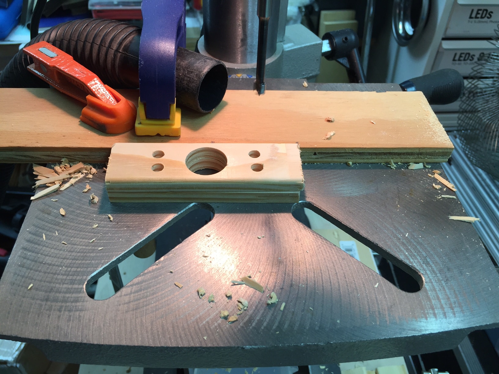
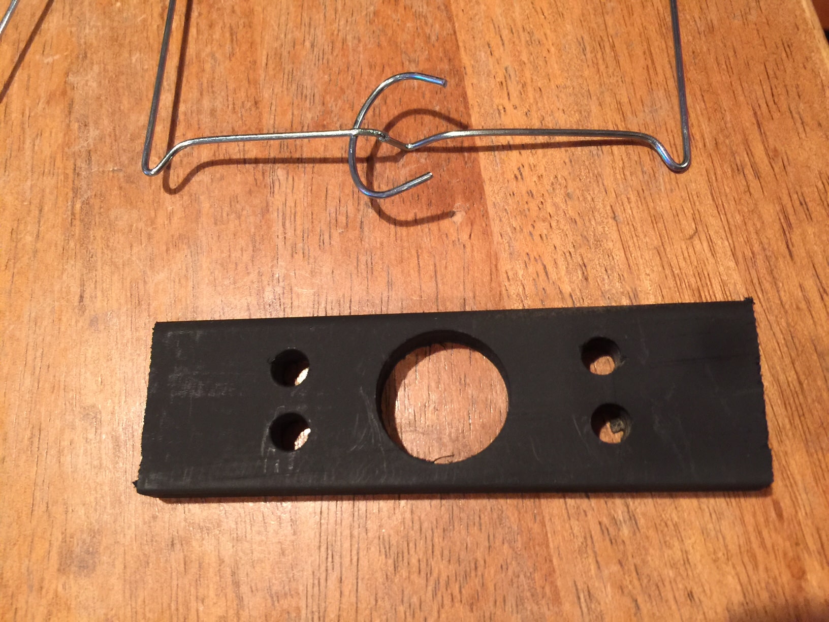
– once I had the china ball lights, including the internal wire frames, I had to design a way to mount the LED to the wire frame. I quickly came up with an idea of using some wood trim, with a few holes in it, which would both attach to the wire frame, as well as allow the attachment of the pixel board. I just used wood door trim from my local hardware store. I was able to get 20 pieces out of a single length of trim. I then set up a jig on my drill press, with measurements, and then drilled the large hole using a forstner bit, for a clean hole. I would not recommend any other bit, given the size of the hole in comparison to the size of the wood trim — the wood would be destroyed by something like a spade bit. Tip: put a piece of wood under the piece you’re drilling, for a cleaner hole on the bottom of the piece.
– next, I attached the pixel board to the wood trim piece. Fortunately, the pixel board had holes on either side. I simply used wire ties
– finally, I attached the wood/pixel combo to the wire frame of the light. It goes on nicely with wire ties. The bottom hook part of the wire frame protrudes nicely down through the large hole in the wood trim piece. Note that I attached the wood trim piece *under* the wire frame, so that the pixel board is pointing straight down into the light.
Testing
– now the fun part: I hooked up all the LEDs on the floor and fired up the Arduino. The Adafruit site has some information on the physical connection for the pixels that they sell, including some basic code.
– As mentioned earlier, I needed to insert power at the 10th pixel in the string. Inserting the power here meant disconnecting the red power input for the 10th pixel and inserting a modular power adapter jack for the input. Then I added another 12V, 2A power supply and power here for testing. This would be modified slightly at installation, but this will allow testing.
– and it all worked. Now I got to work with the code. The Adafruit site provided some sample code, and I found many helps in the Arduino reference pages:
– links to URLs that were helpful:
– adafruit.com
– arduino.cc
– the one about power drain on youtube???
– magnets
– final with wires going in and out of lamps
Installation
– This was a very time-consuming install. Placing the magnets and hanging the china lights was simple, as was connecting the cables between. The most time-intensive part was going up and down the ladder a few times for each lamp and moving the ladder around. I had a fantastic helper, which made it about as efficient as possible. Another time-consuming piece was the creating the custom connection cable between the columns as described above. Since I was doing this part largely by myself, it involved running the cable and then removing it to make the connections, then re-installing it.
– In order to run the second power line to pixels 11-20, I used some red/black zip wire and just routed it back to the FOH booth, along with the control cable from pixels 1-10. That way I could have both power adapters, the Arduino and connections all in one place.
Parts list
– (2) 12V, 5A power supplies
– 36mm square 12V Digital RGB LED Pixels from Adafruit
– 20 sets of male/female, 4-pin connectors. Type doesn’t matter, but the wire gauge should be 22ga or larger.
– heat shrink tubing, 3/16” and 1/2”
– control cable – 22ga or larger. Length dependent upon the application.
– 20ga red/black zip wire for supplying power to pixels 11-20
– Arduino microprocessor – I used the Uno, but a smaller version would probably work
– (2) 15V, 1000uF capacitor – across the power going to each set of 10 pixels, to avoid voltage spikes damaging the pixels
– (2) female power adapter jacks
– 8’ of 1/4” x 1-1/2” door trim or similar
– (20) china lights with wire frames
– (30) magnet hooks; some for the lights and some for the wiring between
– string or twine for hanging the china lights from the magnet hooks
– a bazillion wire ties for making everything tidy


![]()


Leave a Reply